|
Antec Aria mATX Modification Page
|

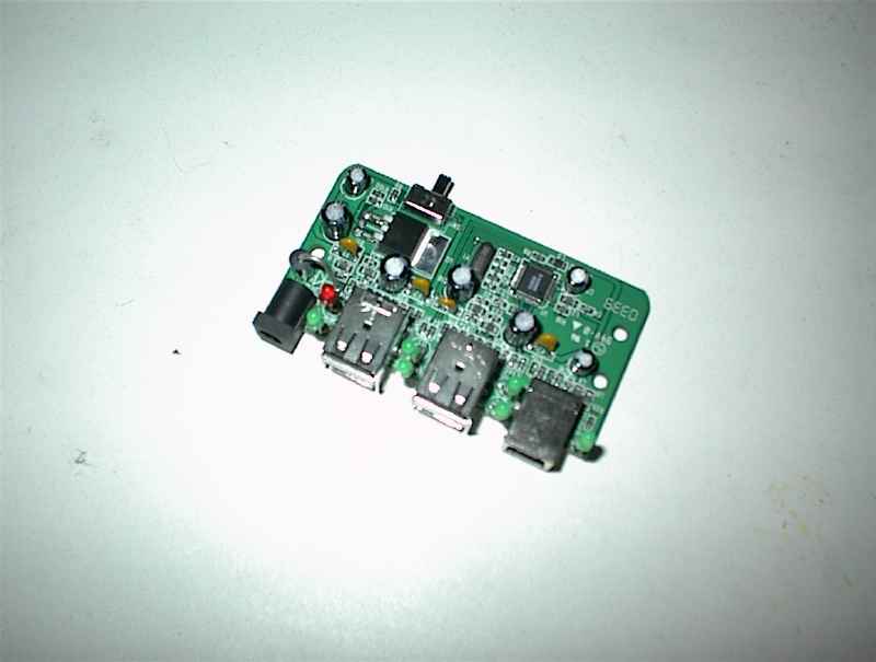
This is my "case-modification", I simply used a TOPCOM 4 port USB hub in order
to get the front-panel USB ports of the
Antec Aria MicroATX case
working on the Pegasos2;
this way a PCI port won't even be occupied and I find that very convenient. You could also buy a
real hub made for internal use (if you can find one) and do something similiar to this...
Well... Atleast it was fun...
I've had this hub for some time without even having a use for it...
Items needed:
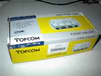
1. TOPCOM 4 port USB hub.
2. Some "crimped" wires. (From f.ex a mobo socket connection)
3. A 4 or 5 pins wide plug for the new cable-end we need to make.
4. A glue-gun.
5. A piece of carton.
6. Some electrical tape.
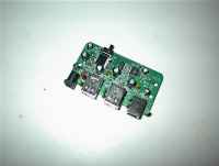
First thing I did was to strip the USB hub out of its liltle casing, then I went
and fetched an old plug with wires that I found in a drawer with some other
junk...
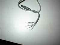
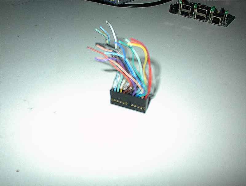
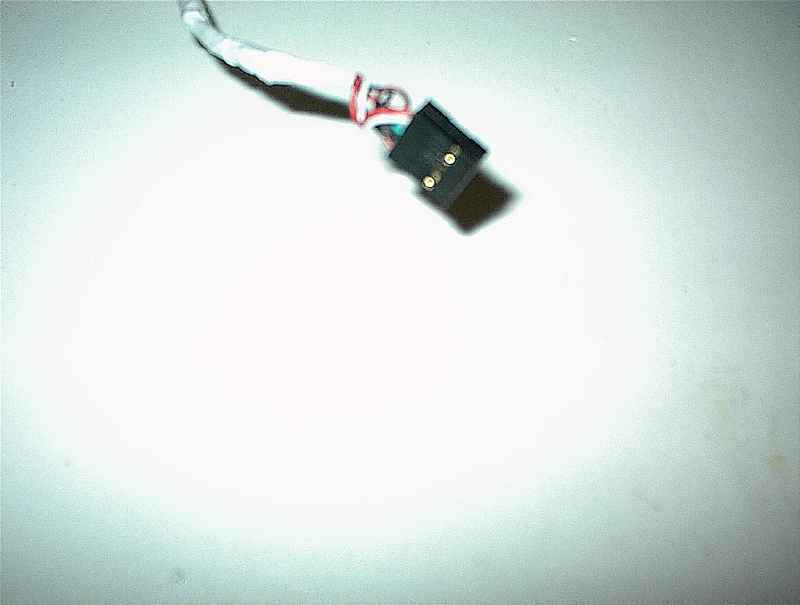
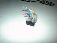
Next thing I had to do was simply to pull a few wires out of the plug; theese
would later be used for the cable as a connection between the motherboard and
the hub. The good thing about theese are that they are crimped and ready for use!
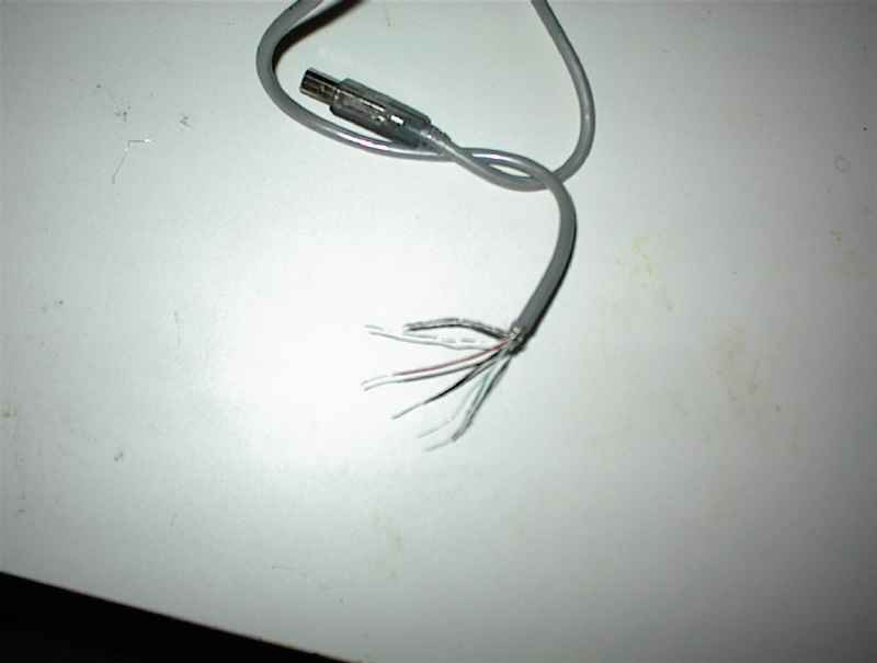
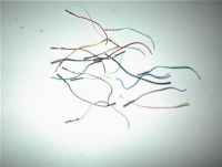
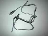
Next, I simply cut the cable provided within the package in two parts and
peeled 4-5cm of the hub-end cable in order to get hold of the red, white, green
and black cables inside... (Peeling their ends also when getting them loose).
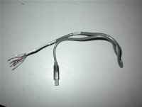
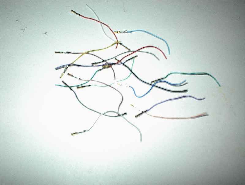
I then connected the crimped cables together with the wires from the peeled hub-cable;
securing each red, white, green and black cable with electrical tape. I fetched an
old 5-pin plug and connected each crimped end into the plug. Getting the right order
here is important. It should be in the order; red, white green, black(gnd),
black(gnd)(if available). Now I could finally connect the hub to the motherboard.
After checking the hub worked correctly and I could connect devices; it was time for
the next step...
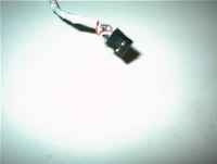
The next thing to do was a little tricky... As my soldering-iron is a bit to big
for soldering cables onto the solder-points on the bottom of the hub; I went for
another approach than soldering.
I concluded that the best way would be to demolish
the "external part" of the USB ports on the hub and connect the cables from the
front-palen USB ports and the cardreader directly onto the card. To do this,
I had to pull the 4 pins on the back of each usb port out of the USB socket on the
hub. I did this by opening the backside of the USB ports and pulling the little
"pin thread" out using a tiny screwdriver. After a while I had pulled 12 pins...
All in all from three USB ports!
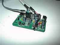
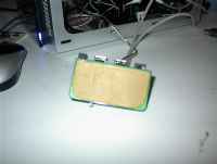
After some investigation it became apparent that the connections needed to be
"stabilized" somehow. Afer all; I didn't want a card reader glitching all the time.
The solution to this was to glue the wiring and connections in place using a
soft-plastic based glue-gun. The big advantage of this is that if you want to
remove the cables in the future, this can be done fairly easy using a sharp knife
or just pulling with a little force. (And even warming the plastic up a bit again.)
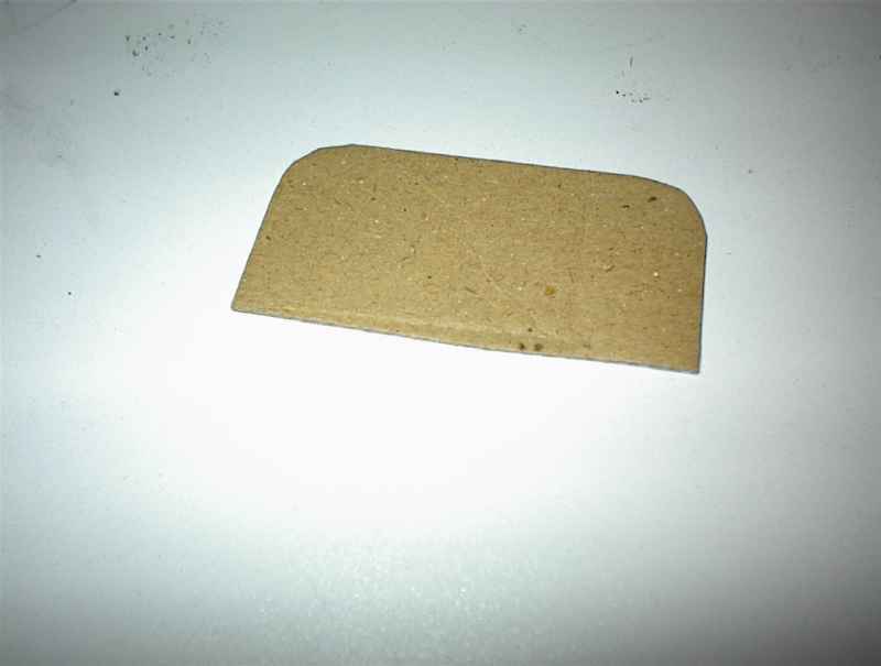
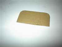
Next thing to do was to cut out a piece of carton and glue it to the bottom
of the hub!
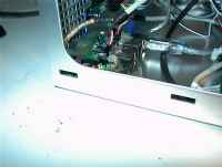
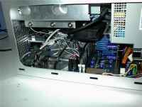
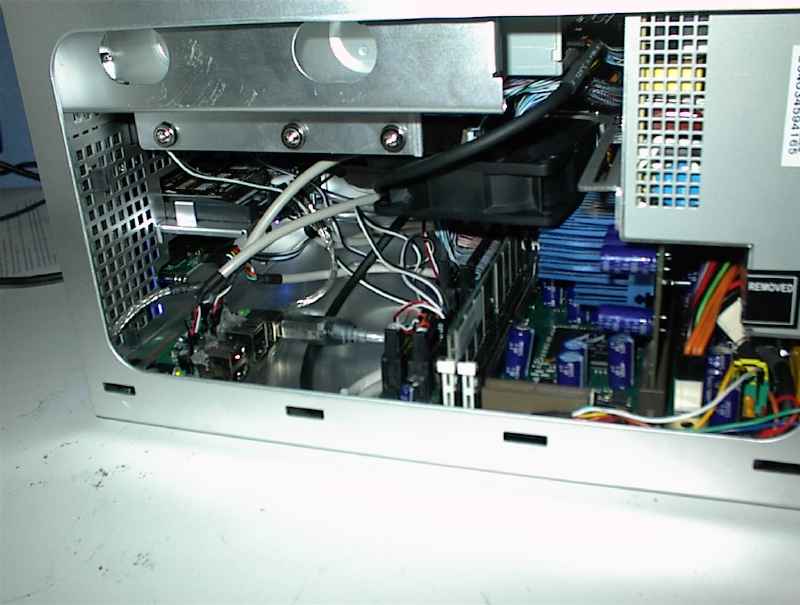
With the whole thing almost done I tested everything one last time to see it still
worked allright, then I just simply put some glue on the backside of the hub
(now with carton on the backside) and glued the hub into the corner of the case; as you
can see on the pictures above.
After connecting all the cables it was all done!
« Previous Page
|
|